

Borescope inspection is an effective method for examining internal surfaces and components that are difficult to access without disassembling equipment. Widely used in aerospace, automotive manufacturing, power generation, petrochemical processing, and industrial maintenance, borescopes help technicians identify visible defects, assess component conditions, and document inspection findings.
From cracks and corrosion to wear, deposits, and foreign object damage, industrial borescope inspection can provide valuable information about equipment condition and potential maintenance requirements.
However, identifying defects accurately requires more than inserting a probe and viewing an image. Inspectors must understand the capabilities and limitations of the equipment, select appropriate inspection parameters, recognize common defect patterns, and document findings consistently.
This guide explains how borescope inspection works, which defects can be identified, how to conduct an effective inspection, and how to select the right industrial borescope for different applications.
Borescope inspection is a visual inspection technique used to examine internal areas that cannot be viewed directly. It allows inspectors to observe components through existing openings, access ports, or narrow passages without unnecessary disassembly.
An industrial borescope typically consists of an insertion probe, an optical system, an illumination source, and a viewing system. Depending on the instrument design, images may be transmitted optically or captured electronically by a miniature camera.
Modern industrial video borescopes commonly provide a display for real-time viewing and may support digital image capture, video recording, probe articulation, and specialized measurement functions.
These capabilities make borescope inspection useful for:
Examining internal mechanical components.
Identifying visible surface defects.
Checking for foreign objects and contamination.
Monitoring wear and deterioration.
Documenting equipment condition during maintenance.
Comparing inspection results over time.
Borescope inspection is generally considered a form of remote visual inspection. It can support maintenance and non-destructive testing programs, but it does not automatically replace other inspection methods when internal defects cannot be reliably assessed visually.
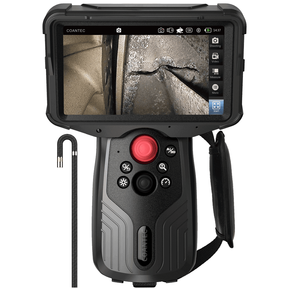
The types of defects that can be identified depend on the component material, defect geometry, surface condition, probe access, illumination, image quality, and inspector experience.
The following are common defect categories encountered during industrial visual inspection.
Cracks can develop because of cyclic loading, thermal stress, fatigue, manufacturing defects, corrosion-related damage, or other deterioration mechanisms.
During borescope inspection, visible cracks may appear as fine linear indications, irregular dark lines, or discontinuities in a component's surface.
Inspectors may look for:
Linear indications that differ from the surrounding surface.
Cracks near corners, holes, joints, or geometric transitions.
Surface discontinuities around highly stressed areas.
Changes in previously documented indications.
Crack identification can be challenging. Scratches, machining marks, seams, deposits, and shadows may resemble cracks in a borescope image.
When a crack-like indication is observed, the inspector should document its location and appearance and follow the applicable inspection procedure to determine whether additional examination is required.
Important: A conventional visual borescope cannot reliably detect every crack. Tight, subsurface, or poorly oriented cracks may not be visible, even when the component appears normal.
Corrosion can affect metal components exposed to moisture, chemicals, elevated temperatures, or aggressive operating environments.
Visible corrosion-related indications may include:
Rust-colored or discolored areas.
Pitting and localized surface damage.
Rough or irregular surface textures.
Oxide scale or deposits.
Localized material loss or flaking.
In high-temperature equipment, oxidation and thermal deterioration may produce surface changes that require interpretation alongside operating history and material specifications.
A borescope can help identify suspicious areas and document visible deterioration. However, color changes alone do not establish corrosion depth, remaining wall thickness, or structural integrity.
Where material loss or remaining thickness must be quantified, an appropriate complementary inspection or measurement method may be necessary.
Wear can occur when components experience friction, repeated contact, inadequate lubrication, particle contamination, or abnormal operating conditions.
Common visual indications include:
Scratches and scoring.
Polished contact surfaces.
Grooves and abrasion marks.
Localized surface damage.
Changes in component geometry that are visible within the available view.
Wear patterns may help maintenance personnel investigate possible causes, such as misalignment, lubrication problems, or contact between moving components.
For example, during engine or gearbox inspection, unusual scoring may justify further examination of the affected component and associated lubrication or operating conditions.
The severity of wear should be evaluated against applicable component limits rather than determined from image appearance alone.
Foreign object damage is particularly important in aerospace, turbine, and other machinery applications where loose objects or debris can affect component performance.
A borescope inspection may reveal:
Impact marks on blades or internal surfaces.
Dents and local deformation.
Chipped edges.
Scratches associated with foreign material.
Loose objects or accumulated debris.
In turbine and engine inspections, identifying the location and extent of suspected foreign object damage can help maintenance teams determine the appropriate next steps.
Inspectors should distinguish actual damage from surface contamination, reflections, and harmless manufacturing features whenever possible.
Deposits can accumulate inside engines, pipelines, heat exchangers, hydraulic systems, and other industrial equipment.
Examples include:
Carbon deposits.
Oil residue.
Sludge and particulate contamination.
Scale and mineral deposits.
Foreign material obstructing an internal passage.
Borescope inspection can help determine where deposits are located and whether they appear to restrict access or obstruct a passage.
However, a visual observation does not always identify the chemical composition of a deposit or establish the underlying cause. Additional testing may be required when contamination type is important to the investigation.
Components may become bent, dented, chipped, displaced, or otherwise deformed because of impact, excessive loads, thermal effects, or operating problems.
A borescope can reveal visible changes in component shape, alignment, or surface condition.
Examples include:
Bent or damaged blade edges.
Dents on internal surfaces.
Chipped material.
Misaligned components.
Visible damage around joints or fasteners.
Because the camera viewpoint and working distance can distort the apparent size or shape of a feature, dimensional conclusions should not be based solely on an uncalibrated image.
Where precise dimensions are required, use an appropriate measurement-capable system and follow the relevant measurement procedure.
A systematic inspection process helps improve image consistency, reduce missed observations, and make findings easier to review.
Before selecting the instrument, determine what must be inspected and why.
Key questions include:
Which component or internal area needs examination?
What types of defects are relevant?
What are the access opening and maximum permissible probe diameter?
How far must the probe travel?
Is image documentation required?
Are dimensional measurements necessary?
Which maintenance procedure or acceptance criteria apply?
A clearly defined inspection objective helps determine the appropriate probe design, viewing direction, illumination, and image quality requirements.
Different inspection environments require different equipment configurations.
Consider the following factors:
Probe diameter: The probe must fit through the access opening without damaging the instrument or the component.
Working length: The insertion tube must reach the inspection target while allowing sufficient control.
Probe articulation: A steerable tip may be necessary when the target is not directly visible from the insertion path.
Image quality: The optical system and image sensor must provide adequate detail for the defects being investigated.
Viewing direction: Forward-viewing and side-viewing configurations can suit different inspection geometries.
Illumination: Adjustable lighting can help reveal surface details and reduce underexposure, glare, or distracting reflections.
Environmental compatibility: Verify applicable limits for temperature, moisture, chemical exposure, and ingress protection.
The most suitable borescope is the one that meets the actual inspection requirements rather than simply having the largest number of features.
Before beginning the inspection, verify that the instrument is in good working condition.
Preparation may include:
Checking the probe and insertion tube for damage.
Cleaning the distal-end lens using the manufacturer's approved method.
Confirming that the display and illumination operate correctly.
Verifying articulation controls where applicable.
Checking batteries, storage capacity, and recording functions.
Confirming that the equipment is suitable for the intended environment.
The component must also be prepared according to the applicable safety and maintenance procedures. Equipment should be isolated or placed in a safe condition whenever required.
Never insert a conventional inspection scope into an operating or hazardous environment unless the instrument and inspection procedure are specifically designed and approved for that use.
Introduce the probe through the designated access point and advance it gradually.
Avoid excessive force, sharp bends, and movements that could damage the insertion tube or the component being inspected.
Where an articulating probe is used, adjust the tip gradually to obtain a useful viewing angle.
Maintain awareness of the probe's position and orientation. This helps prevent accidental contact with sensitive surfaces and makes it easier to identify the location of observed defects.
Once the inspection target is visible, optimize the image before making judgments about surface condition.
Useful adjustments may include:
Probe orientation.
Working distance.
Illumination intensity.
Focus, where adjustable.
Image brightness and contrast, where supported.
Excessive illumination can produce glare, while insufficient illumination can obscure surface detail. Reflections from polished metal may also create misleading bright or dark areas.
When an indication is unclear, reposition the probe or change the viewing angle to determine whether the feature remains visible.
Inspect the relevant surface in a consistent sequence rather than moving the probe randomly.
For example, a component may be divided into identifiable sections, with each section examined and recorded in turn.
Look for:
Cracks and surface discontinuities.
Corrosion, pitting, and oxidation.
Scratches, scoring, and wear.
Foreign object damage.
Deposits and contamination.
Deformation or displaced components.
Compare observations with the applicable inspection criteria and any previous inspection records.
If an area cannot be viewed adequately, record the limitation instead of assuming that the absence of a visible defect means the area is free from damage.
When documentation is required, capture images that clearly show both the indication and its context.
A useful inspection record may include:
Equipment identification.
Component and inspection location.
Date and inspection procedure.
Borescope model and relevant probe configuration.
Image or video references.
Description of each observed indication.
Measurement results, where appropriate.
Areas that could not be adequately inspected.
Recommended follow-up actions according to the applicable procedure.
For critical equipment, consistent image framing and location references make it easier to compare current observations with previous inspection results.
After the inspection, review the recorded images and observations against the applicable acceptance criteria.
Classify findings according to the organization's inspection procedure. For example, the report may distinguish acceptable conditions, indications requiring further review, and confirmed defects that require action.
Do not assign defect severity solely from how dramatic an image looks. The evaluation should account for component-specific limits, the nature of the indication, and any required confirmatory testing.
Accurate defect identification depends on both instrument performance and inspection technique.
A defect may be difficult to recognize when the probe looks directly along its length or when reflected light obscures its edges.
Changing the viewing angle can reveal surface irregularities that are less apparent from another direction.
This is particularly useful when examining narrow grooves, blade edges, internal corners, and curved surfaces.
Lighting conditions can influence the visibility of cracks, scratches, corrosion, and deposits.
Adjust illumination to minimize glare while preserving sufficient detail. When possible, compare the appearance of a suspected indication under more than one viewing angle or lighting condition.
If the probe is too far from the target, small features may occupy too few image pixels to be distinguished reliably.
If it is too close, the target may become difficult to focus on or the field of view may become too limited.
Follow the instrument manufacturer's guidance and evaluate image clarity under representative inspection conditions.
Machining marks, seams, reflections, shadows, dirt, and normal manufacturing variations can resemble defects.
Before recording a suspected crack or other discontinuity as a confirmed defect, inspect it from different angles where possible and compare it with applicable component documentation.
If uncertainty remains, document the indication and request further evaluation using the relevant inspection procedure.
Some industrial video borescopes support dimensional measurement through specialized optical or software-based techniques.
These capabilities can help evaluate certain visible defects, but measurement suitability depends on the instrument, target geometry, surface visibility, calibration or verification requirements, and operating procedure.
Not every video borescope supports measurement, and a measurement function should not be assumed to provide reliable results for every type of defect.
Aircraft engine inspections may involve compressor blades, turbine blades, combustion chambers, and other internal components.
Borescopes can help maintenance personnel examine accessible internal surfaces and document visible indications without unnecessary disassembly.
Common areas of interest include cracks, impact damage, erosion, deposits, and other changes in component condition.
Inspection procedures and acceptance limits must follow the applicable engine maintenance documentation and aviation requirements.
Gas turbines operate under demanding mechanical and thermal conditions. Internal inspection can help identify visible deterioration and support maintenance planning.
Borescope inspections may focus on turbine blades, compressor components, combustion areas, and other accessible internal surfaces.
Image records can also support comparisons between scheduled inspections, helping maintenance teams track changes in observed conditions.
In automotive applications, borescopes can be used to inspect cylinder walls, piston crowns, valves, gearboxes, and other internal mechanical components.
Visible scoring, deposits, impact marks, and surface damage may provide useful clues during troubleshooting.
A compact probe can be particularly valuable when access is limited and disassembly would increase inspection time.
Industrial borescopes can support the visual examination of accessible internal passages, equipment cavities, and selected mechanical components.
Depending on the application, inspectors may look for corrosion, deposits, foreign material, surface deterioration, or mechanical damage.
Instrument suitability must be confirmed for the specific environment. Ordinary industrial video borescopes should not be assumed suitable for explosive atmospheres, pressurized systems, or chemically aggressive environments.
Inspection scopes may help examine accessible tube interiors, internal surfaces, and other confined spaces.
Potential observations include deposits, corrosion-related changes, obstructions, and visible mechanical damage.
Where wall thickness, internal leakage, or subsurface defects must be assessed, complementary inspection methods may be necessary.
Modern industrial video borescopes can improve inspection efficiency when their features are matched to the task.
A suitable imaging system helps inspectors observe surface details and record findings for later review.
Actual performance depends on the camera sensor, optics, illumination, image processing, and inspection conditions.
Articulation allows the operator to change the direction of the distal end on supported models.
This can make it easier to inspect surfaces around bends, behind obstructions, or at angles that would otherwise be difficult to access.
Adjustable lighting can help the operator adapt the image to different surface finishes and working distances.
Appropriate illumination is especially important when inspecting reflective metal components or uneven surfaces.
Digital recording supports inspection reports, maintenance records, and comparisons between inspection intervals.
When recording images, ensure that the location and context of each observation can be identified.
Selected video borescopes provide tools for measuring certain visible indications or component features.
These functions may support maintenance assessments, but the measurement method must be appropriate for the target and the required accuracy.
Different probe diameters, working lengths, articulation capabilities, and viewing directions allow inspection equipment to be configured for different applications.
Choosing the correct probe configuration is often as important as choosing the display or imaging system.
Although borescope inspection provides valuable visual information, it has important limitations.
Limited line of sight: The inspector can only evaluate surfaces that are adequately visible to the probe.
Resolution limitations: Small defects may not be distinguishable when the image quality, working distance, or lighting is inadequate.
Surface-related ambiguity: Reflections, deposits, and machining marks can resemble defects.
Limited dimensional information: An ordinary image does not establish exact defect dimensions or remaining material thickness.
Subsurface defects: Conventional visual inspection generally cannot identify defects that do not produce a visible surface indication.
Environmental restrictions: Probe materials, optics, electronics, and articulation mechanisms have specified operating limits.
For these reasons, borescope inspection should be integrated into an appropriate inspection program. Other methods, such as ultrasonic testing, eddy current testing, dye penetrant testing, or radiographic testing, may be required depending on the material, defect type, component geometry, and applicable acceptance criteria.
Before purchasing an industrial borescope, evaluate the inspection requirements in detail.
| Selection factor | What to consider |
|---|---|
| Probe diameter | Must fit the available access opening |
| Working length | Must reach the target while remaining controllable |
| Articulation | Determines how easily the operator can inspect around obstructions |
| Image quality | Must be sufficient for the expected defect size and working conditions |
| Illumination | Must reveal relevant surface details without excessive glare |
| Viewing direction | Should match the geometry of the inspection target |
| Recording | Useful for reports, traceability, and repeat inspections |
| Measurement | Required only when the application needs supported dimensional measurements |
| Environmental suitability | Must meet applicable temperature, moisture, and chemical exposure requirements |
| Service and support | Includes maintenance, repair, accessories, and technical assistance |
For applications involving small cracks or critical components, evaluate the instrument using representative samples whenever possible. A demonstration under realistic working conditions can reveal limitations that are not obvious from a specification sheet.
A borescope can reveal visible surface indications such as cracks, corrosion, wear, scratches, foreign object damage, deposits, and deformation. Detection depends on visibility, probe access, image quality, and the inspection procedure. It cannot reliably detect every internal or subsurface defect.
A borescope may reveal cracks that are visible from the inspected surface. However, tight cracks, subsurface cracks, or cracks hidden by geometry or contamination may not be visible. Additional testing may be necessary to confirm an indication or establish defect dimensions.
Borescope inspection is a form of remote visual inspection and can be part of a non-destructive testing or condition-monitoring program. Its suitability depends on the inspection objective and applicable requirements. It does not replace other NDT methods when those methods are needed to detect or characterize defects.
Inspection frequency depends on the equipment type, operating conditions, maintenance program, manufacturer recommendations, applicable regulations, and previous findings. There is no single inspection interval suitable for every industrial application.
Some advanced video borescopes offer specialized measurement capabilities. Whether a particular defect can be measured accurately depends on the instrument, viewing conditions, target geometry, and measurement procedure. Standard visual images alone should not be treated as precise dimensional measurements.
Direct visual inspection generally allows the inspector to observe accessible surfaces without an optical extension. Borescope inspection extends visual access into confined or enclosed areas using a probe and optical or electronic imaging system.
Use appropriate illumination, adjust the viewing angle, maintain a suitable working distance, inspect the indication from multiple perspectives where possible, and compare observations with relevant documentation. If uncertainty remains, record the indication and follow the applicable evaluation procedure.
Borescope inspection is a valuable technique for examining inaccessible internal surfaces, identifying visible defects, and documenting equipment condition.
By understanding common defect types, following a systematic inspection procedure, optimizing image quality, and recognizing the limitations of visual inspection, technicians can obtain more consistent and useful inspection results.
Selecting the right industrial borescope also plays an important role. Probe diameter, working length, articulation, illumination, imaging performance, recording capabilities, and environmental suitability should all be considered before purchasing inspection equipment.
For demanding industrial applications, a well-planned borescope inspection can support maintenance decisions, reduce unnecessary disassembly, and provide valuable evidence for further evaluation.
Copyright © 2025. Coantec Ltd. All rights reserved. sitemap